The complete story charting the development of Audi's 3.7 litre V6 diesel turbo engine that powers the R18
Downsizing was the buzzword when Audi Sport was developing its new engine for the 2011 Le Mans 24 Hours. The ACO had outlawed the big 5.5-litre engines used previously and forced the manufacturers to think small.
For diesel engines, the upper displacement limit was set at 3.7 litres and the maximum number of cylinders set to eight, while petrol engines were restricted to normally aspirated 3.4 litres and 2-litre turbo.
The reasons for this reduction on the maximum capacity for diesel engines were primarily those of safety and equivalency. Concerns were being raised about the speed of the works LMP1 cars as Peugeot and Audi were
locked in a development war. This led to a dramatic reduction of the lap times in qualifying, but also increasingly during the race to within striking distance of the ‘eternal record of 3m 14.8s from 1985 where maximum speeds
of more than 400km/h were recorded at Le Mans.
Audi first took the decision to develop a new Le Mans Prototype engine for 2011 back around the time of Le Mans in 2009. The successful R10 V12 and R15 V10 predecessors supplied a starting point which allowed the German
engineers to develop the new unit in just 20 months. For the new design, it was imperative to assess whether the chosen concept, which explored previously unknown technical territory in many aspects, could also be successfully
developed in the short development time.
Usually the engine regulations and rulebook for the car are fixed before design work begins on a new project but in this case only guidelines for engine power and maximum displacement had been issued, which left the
engineers to take a gamble.
At the start of the project the Audi Sport engineers considered using a high efficiency spark ignition engine, but again opted for a diesel after early evaluation of the concepts.
The guidelines issued allowed the Audi engineers to define some performance targets for the new engines. The expected power was fixed as a broad premise in the regulations – such as they were. The restrictor diameter
was also defined accordingly in the same rules, and the operating range along with the maximum boost pressure were effectively predefined. So, the targets set were: power exceeding 520PS (382kW), torque greater than 900Nm
in a wide, useable RPM range (in order to be able to use a six-speed gearbox efficiently); total engine weight significantly less than 200kg, and stiffness when installed in-car as a fully stressed design, with supporting
elements. The restrictor diameters and boost pressures were reduced still further for 2011. This resulted in a power and torque reduction and a slight shift of the power point in the rev range.
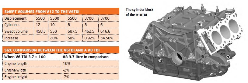
The next question was; what size and shape would this engine be? The definition of the number of cylinders was also on the agenda at the beginning of the concept stage. An eight-cylinder engine would have had the advantage
of being able to transfer the enormous amount of experience gained from the area of the 12-cylinder R10 engine. However, Audi was convinced that a six-cylinder block had greater potential with regard to frictional losses,
weight and compact dimensions. The targets for the new engine resulted from the demands to reduce engine dimensions and to be able to change the car’s weight distribution. The overall dimensions of a 3.7-litre V6TDI engine
showed the advantage of its shorter length, but a V8 engine could be fitted lower in the car achieving lower height and width dimensions.
The regulations also permit engines with a capacity of less than 3.7 litres. With the weight and size of the engine crucial to overall car performance, a smaller capacity was also considered but – as was the case with
the R15 engine – the choice of a 3.7-litre displacement was made with the underlying intention of keeping the specific load as low as possible. With increasing displacement, the engine’s effective mean pressure sinks for
the same attainable power (air mass).
The next step was to design a block. It would have to be as compact as possible and lightweight. Its design is also heavily influenced by many other factors. In order to reach the weight target, the majority of the engine
had to be manufactured from light metal alloys and – at the same time – be able to withstand combustion pressures permanently above 200 bar.The R18 V6 cylinder block is manufactured from hypoeutectic alloy using the
low-pressure sandcasting method. The cylinders themselves are Nikasil coated. Completely new engine block architecture was required due to the large cylinder bank angle. The cast water channels, with a fork to the heat exchanger,
have only a joint to the water cooler in an otherwise closed system. The relevant oil galleries are integrated in the block for piston cooling. The crankcase below the main bearing centre line – the so-called bedplate – is manufactured
as complex, heavy-duty cast component. The precision casting blank has equally high strength (RM 35 MPa) and ductility owing to the directional solidification. The minimum wall thickness is less than 2mm.
The final block design featured a slightly long stroke as a result of piston loads, engine size/installed height and combustion chamber thermodynamics. The installation height of the engine is influenced substantially
by the stroke. The stroke increased by five per cent when compared to the V10 and is accounted for by the increase in the crankshaft centre-line from the bottom plate. The 120-degree cylinder bank angle led to the Audi
engine achieving a very low mounting position and therefore a low centre of gravity.
It was also designed specifically to suit the steel piston’s lower compression height. Due to the larger bore of the V6TDI, the piston area loading is increased by approximately five per cent for the same ignition
pressure. Meanwhile, the 120-degree cylinder bank angle is a result of the following points: lowering of the centre of gravity, layout and drive of ancillary components, firing interval and the mono-turbo exhaust
layout. With this cylinder bank angle, the bedplate can still be connected extremely well to the crankcase. The cylinder spacing was adjusted to suit the increased bore so that the land width could be retained. As
a result, the closed-deck engine block achieves the required stability.
KEY ENGINE ELEMENTS
At the heart of the engine is the cranktrain, topped with some innovative steel pistons, which are one of the key elements of this engine. Due to the high piston loads generated in a race engine, the maximum
load limit for the aluminium piston with a fibre-reinforced bowl rim was achieved during development of the V12TDI. Steel pistons were fitted to the R15 V10TDI from the very beginning. The larger bore and increased
loads on the R18 V6TDI piston necessitated extensive analysis of the thermal management of the piston and piston rings.
The piston is manufactured from heat-treatable steel. This material combines the properties of high temperature resistance and good thermal conductivity with excellent machining properties. In addition to the
higher temperature resistance, the steel piston has the advantage that the top-land is smaller than that of an aluminium piston. Owing to the greater transferable force in the pin bore, the gudgeon pin fitted
to the steel piston can be considerably shorter, which in turn allows a weight reduction. As a result, a weight saving is even achievable when compared to the aluminium piston. The steel piston, made by Mahle,
has a combustion bowl developed specifically for this application. The high thermal loads made the use of two piston spray nozzles necessary – one for the piston base and the other for the cooling channel.
The reduction in displacement and number of cylinders led to a direct increase in the litre and/or cylinder power and therefore, inevitably, to higher piston loads. In conjunction with the extremely short development
time of the engine, the reliability of the piston had to be proved by calculation at an early stage of the design.
The design of the piston bowl, the lowest possible compression height as well as minimum weight are actually contrary to achieving the stiffest possible and operationally reliable design of the piston, which is
subdivided into different disciplines. In addition to the actual stress analysis for the piston and liner, a perfectly functioning ring package is also required.
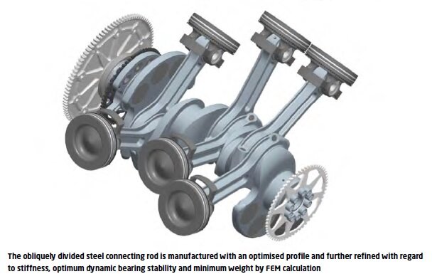
The crankshaft was designed around several key areas: the bearing load through the RPM range and load spectrum (ignition pressure and inertial forces); torsional and bending stiffness; free moments of the first
and second order; vibration sensitivity and lightweightness.
Its essential dimensions were determined using bearing load and hydrodynamic lubrication gap calculations in conjunction with FEM. In this way, the diameter and width of the main and connecting rod bearings were
defined according to operational demands, and the crankshaft webs made for greater stiffness of the journal connection.
Because of the engine’s design, the free moments of the first order acting outwards can only be minimised by balance masses on the crankshaft.
The weight target for the entire engine did not, however, allow complete balancing of the free moments, but the resulting vibrations caused by the imbalance are acceptable for a race engine. An additional weight
on the front end of the crankshaft and an extra web ahead of the gear drive facilitate efficient compensation due to the large centre-to-centre distance. The crankshaft’s stiffness is so high that a vibration damper
could be omitted.
On the drive-side, a light steel flywheel transmits the torque to the clutch. Teeth with straight-sided serrations replaced the flywheel flange previously used. In this way a conventional, high-strength crankshaft gear
could be used.
An incremental toothed gear positioned alongside the crankshaft drive gear supplies the impulse for the Bosch Motronic rotational speed signal. Another incremental toothed gear at the front end of the crankshaft gives
a redundancy of the rotational speed recognition.
At the top of the engine, the design owes a lot to its predecessors, especially the V10 engine. In the first development stage, the cast aluminium cylinder head design was tested in a single cylinder engine. The basic
single cylinder unit used in the development of the V10 was modified rather than a new unit built. Some components were created quickly using the rapid prototyping process to increase the speed of development. The single
cylinder engine was used for the main tasks in the combustion process development, and endurance tests.
But it is not the case that the V10 heads were carried over to the V6, not least as they had two cylinders too many. Many areas had to be re-dimensioned due to the increased loads caused by the larger bore. The included
valve angle was optimised and the valve enlarged so that the bore diameter could be used to its maximum.
Further development of the ports and port positions were verified together with the definition of the included valve angle on the single- cylinder cylinder head using flow boxes and simulation. The basis for this was the
previous engine on which the systematic for the swirl flow optimisation was carried out.
VALVE TALKING
Two inlet valves and two exhaust valves are aligned parallel to the cylinder axis. The valve seat rings are manufactured from sinter alloys that were specially designed for the high loads. The valve guides are produced from
copper-beryllium alloy. The valve gear consists of natrium-filled steel valves, conical valve springs and finger followers. The injector duct positioned centrally at the cylinder head middle is well supported by ribs in the
oil chamber and therefore ensures a stable combustion chamber plate.
The cylinder head cover with the engine mounting points is machined from solid billet for strength reasons. Thanks to the integration of the camshaft bearings in the cylinder head cover, the cylinder head has a particularly
high stiffness level in the upper area. This allows the introduction of suspension forces via the monocoque and/or the gearbox.
Through optimisation measures, it was possible to omit a mounting point between the cylinder head and the monocoque. In the area of the gear wheel housing, a part of the cover and the housing was replaced by a carbon-fibre
part to reduce weight.
The camshafts are steel and are hollow drilled for weight reasons. The cam lobe profile was modified when compared to the R15 V10TDI. Greater cam lift and modified valve timing were required to optimise the new combustion
process.
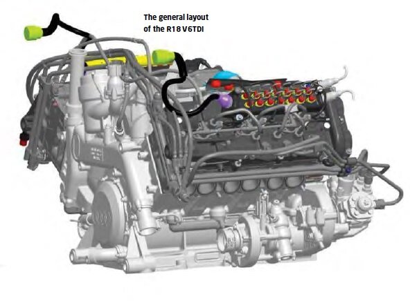
Because of the engine’s short length, it was not possible to position the high-pressure injection pumps alongside the engine on the timing gear housing. A radical change to the camshaft and pump drive was the result.
The gear drive was repositioned on the engine’s power output face and the CP4 hydraulic pumps are located towards the rear.
The twin pump arrangement balanced the peak torque produced by the hydraulic pumps – but for increased weight when compared to the single pump design.The layout of the gear drive on the clutch side of the engine ensures
that the gear drive runs relatively smoothly, and that only low alternating torque occurs.
In addition to the camshafts, gears also drive the oil and water pumps and the high-pressure fuel pumps. The needle roller bearing steel gears are supported in the housing using floating axles. One floating axle per
cylinder bank simultaneously assumes the function of compensating for tolerances and height differences in the cylinder head. The synchronously injecting hydraulic pumps are integrated into the gear drive with a ratio
of 0.75. By reducing the drive speed, a high-load layout was possible for the highest injection pressures.
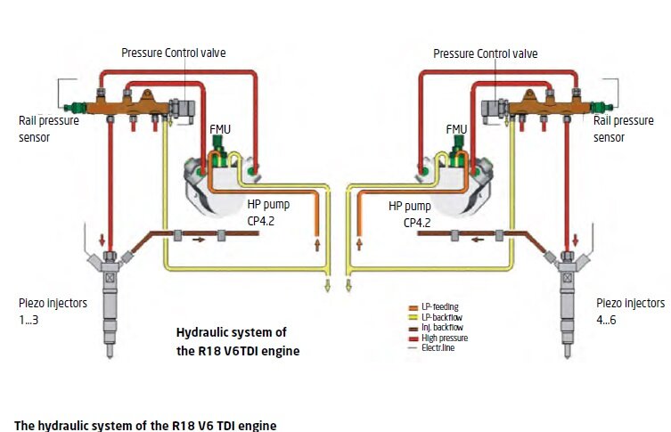
The piezo injectors are tailored to suit the engine. The nozzles were designed for the required output and tailored for the selected combustion process parameters through elevation angle, number of holes/type
and nozzle protrusion. The low and high-pressure fuel systems are modified to suit the engine installation. Quick-release couplings in the feed and return circuits form the interface to the car. The fuel tank
system with electric low-pressure supply pumps (lift pumps) was newly developed for the R18.
The inlet manifold length assumes a part of the charge exchange work, and is therefore a part of the engine calibration. In 2011, a relatively short inlet manifold equipped with a small plenum volume was used.
The cross-sections are tuned to the inlet port area of the cylinder head. For 2012 the setup was reworked and a significantly larger induction manifold length used. The boost pressure monitoring system/sensors
supplied by the organisers ACO/FIA are located on the inlet manifold. The inlet manifolds and the plenum chambers are manufactured from carbon-fibre for weight reasons.
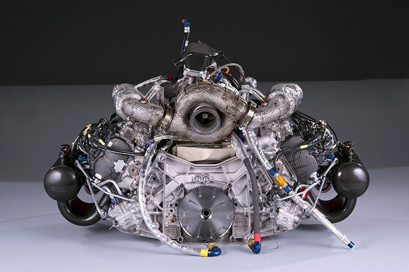
HOT SIDE INSIDE
With the ban of ‘snorkel like’ air intakes – ie air inlets protruding above bodywork parts – a central air intake was the only efficient solution for an LMP1 coupe. Two closed monocoque Le Mans Prototype
racecars had previously been designed and built by companies within the VW group – the Audi R8C from 1999 and the Bentley prototypes between 2000 and 2003. The difficulties of achieving good airflow with
low resistance for a twin turbo system installed on the side of the engine were known from the Bentley project. Therefore, in order to fully exploit the dynamic air pressure, great value was attached to
achieving a very short, fully streamlined route for the intake air.
The following considerations were obvious to the Audi engineers: a central turbo layout, exhaust channels mounted in the engine's V, a wide V angle to make space for the turbocharger and a large cylinder
bank angle.
Several concepts were developed for the inner V area – especially the exhaust system within the narrow constraints of the aerodynamic outer bodywork. A fundamental question was whether a single turbocharger
can generate the same or even better initial response than a twin turbo system.
The calculations made by Honeywell Turbo Technologies indicated that the mono turbo with VTG was the superior concept. On top of this came the significantly lower air mass due to the reduced restrictor
size, when compared to preceding engines, which made a mono turbocharger possible.
A consequence of ‘hot side inside’ is an externally mounted intake system with very short charge-air piping, which is advantageous for improved response characteristics. The unfiltered-air side of the
engine induction system is made along the car’s roof. The ducting incorporates a low pressure loss air filter and airflow to the restrictor is optimised. Exploiting the dynamic pressure at high vehicle
speeds generates a marginal increase in mass flow rate. The air is compressed to the permitted boost pressure in the compressor and enters the intercooler at temperatures of up to 200degC. After cooling,
it reaches the induction system through a short carbon-fibre connecting pipe.
Another aim of the externally mounted intake system was to achieve the lowest possible blockage of the radiator exhaust air. A result of the centrally mounted turbocharger was that a very simple and light exhaust
system layout was possible with the DPF at the back of the car. This was changed for the 2013 season to allow the development of a 'blown diffuser' (see RCE V22N6).