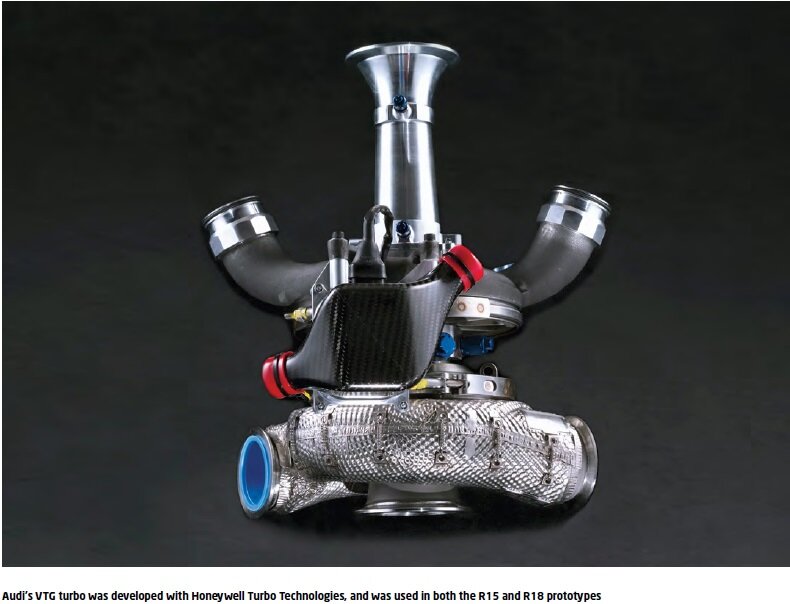
At the heart of the 'hot side inside' concept is the single turbocharger. A turbocharger with variable turbine geometry (VTG) was previously used on the R15. When compared to a conventional wastegate turbocharger,
the advantages of this system, with an adjustable guide vane ring upstream of the turbine inlet, are mainly reflected in the significantly better boost pressure build-up in the lower rev range, in the dynamic, in
response and also in more favourable fuel consumption due to the improved scavenging ratio.
The knowledge and experience gained with the VTG turbocharger were particularly important in the making of the decision to consider a mono turbocharger for the V6 for the R18, to start a completely new development
and to race it.As the entire air mass flow had to be generated by a single turbocharger, the result was a larger, heavier and inevitably more sluggish turbocharger. The larger dimensions, and the greater moment of
inertia of the rotating components, led to a one of the most important turbocharger development points – optimisation of the response characteristics.
A significant advantage was the change from a 5-speed gearbox to 6-speed, so the turbocharger could be designed for a narrower rev range. The targets set for the new turbo were lightweight design, boost pressure
increase after pit stop, hairpin bends or after safety car phases, and temperature resistance above 1000degC.
Almost 3.7 kg could be saved through component optimisation and material changes in the first year. At the same time, the moments of inertia of turbine and compressor impeller could be reduced, which led to a
considerable improvement of the response characteristics.
In addition to simple measures, such as simultaneous operation of the throttle and brakes to increase load and, as a result, to increase the exhaust gas energy by faster response of the ATL, a good opportunity
presented itself to increase the exhaust gas temperature and thus ensure faster boost pressure build-up by retarding the main injection and/or post-injection. Indispensable for this was the previously described
packaging of the exhaust pipes and turbine housing as well as the high-temperature resistance of the turbocharger for the lowest possible radiation losses of the exhaust gas energy.
The development of this unit was carried out in cooperation between the Audi Sport Engine Development department and Honeywell in Brno (Czech Republic) at the strart of the R18 concept. The design was tailored for
the mass flow limited by the restrictor upstream of the compressor. Another design criterion exists in the boost pressure limitation stipulated by the regulations. Exhaust temperatures, mass flow and control dynamics
determine design on the turbine-side. The exhaust temperature above 1000degC required for maximum engine power was a development target from the beginning and was implemented.
The turbocharger concept differs through its design as mono-turbo supplying two cylinder banks. The volute curl of the compressor and the turbine both have an influx flow field of approximately 180 degrees.
Particularly challenging was the development of the turbine for high exhaust temperatures, and precise boost pressure control immediately following the short gearshift times. The blades and levers of the
turbine guide blades are high-temperature steel alloys.
Blade control was made via a linear actuator with very high adjustment speeds, regulated by the engine control unit.
The turbocharger is mounted on ball bearings. The bearing housing is supplied with pressurised oil and drained comby one stage of the dry sump scavenge pump. All elements are equipped with quick-release couplings, allowing rapid replacement during races.
The turbine impeller sealing system to the centre housing, and the centre housing itself, were also new developments. The introduction of water-cooling to the rear wall of the turbine led to the
sealing element components in the turbine area being subject to significantly lower loads. The cooling water flow was taken from the oil-water heat exchanger system via a parallel connection.
An additional water pump undertook the water-cooling for the ‘hot’ stop in the pits.
During development for 2012, the bearing housing was lightened by the substitution of material. The exhaust system’s primary pipes are tuned in length and diameter to achieve good gas exchange and optimised flow to the turbine.
The integration of compensators between the 3-into-1 collector and the turbine inlet was necessary because of thermal expansion, and the connection of the banks in the turbocharger. The turbocharger in the inner 'V'
is mounted on articulate couplings to the crankcase.
Through trim optimisation on the impeller, the map characteristics for higher mass flows could be moved and, as result, the nominal power point shifted into the area of optimum efficiency. Because of this, and due
to improvements to the transition between impeller and housing, significant advantages in consumption were achieved with corresponding power gains.
Another measure to optimise the turbocharger in part-load operation was the new development of an electromechanical VTG actuator for the mono turbocharger to replace the production actuator previously used.
The development was made in cooperation with the company MEGA-Line. Several targets for the new actuator were to achieve the optimum VTG position as quickly as possible under all dynamic driving and load conditions,
to reduce the weight and create the possibility to expand the software functionality. The mechanical adjustment speed was increased by more than 50 per cent, the force level doubled and, at the same time, the weight
reduced by almost 40 per cent. To expand the software functionality the previous communication interface was changed from PWM to CAN. The in-house generated programme code could thus be expanded and optimised with regard
to robustness, reliability and diagnostic capability.
DYNAMOMETER
Audi set itself the goal in 2012 of becoming the first manufacturer to win the 24h of Le Mans with a hybrid car. To be able to achieve this goal a new car concept, the Audi e-tron quattro, was developed.
The rear axle of the Audi e-tron quattro is powered by a combustion engine and the front axle by a Motor Generator Unit (MGU). An electromechanical flywheel accumulator acts as energy storage device for
the Motor Generator Unit. A new drivetrain dynamometer was constructed at Audi in 2011 to enable this concept to be developed. To accommodate the dynamometer in a test cell, the original dynamometer
building had to extended from its original layout. The dynamometer is equipped with four wheel motors and/or two axles. The wheel motors, which are permanent-magnetic synchronous couplings, permit wheel
speeds of up to 3,700 rpm as well as wheel torques of up to 4000Nm to be simulated. The installed wheel machine power is 1200 kW.In addition, the dynamometer is also equipped with a battery simulator that
can be used to simulate single hybrid components.
The exhaust manifold is equipped with a high-heat insulating cover to minimise heat dissipation into the engine bay. The turbine is largely thermally insulated. Gas flow to the DPF located directly behind
LOADSthe turbine was optimised to guarantee uniform pressurisation of the particle filter. The DPF discharges via a short exhaust pipe that exits at the back of the car. The proven DPF substrate from the R15
was retained. The dimensions were optimised and tuned for low pressure loss for the required conversion rate.
INSTALLATION
To develop a diesel engine as a thoroughbred race engine is a great challenge from the very beginning. The task is further complicated by the need to integrate the engine perfectly in the very small overall
package of a sports prototype.
As with the R15, the engine and car were designed as a harmonic unit without weak points. To obtain the ideal suspension setup, all the car’s stressed components must have an equally high stiffness, which
is why the engine is mounted rigidly as a fully stressed member between the monocoque rear bulkhead and gearbox. The stiffness could be further increased by the use of very light backstays between the monocoque
and gearbox casing. The installation of a turbo engine is significantly more complex than that of a normally aspirated engine due to the air ducting. The intercoolers and water coolers are located on both sides
of the monocoque in close proximity to the engine – the result is low-loss flow for low duct volumes. The car side cooling air ducts were optimised in the wind tunnel and ensure very efficient cooling of the charge
air and water.
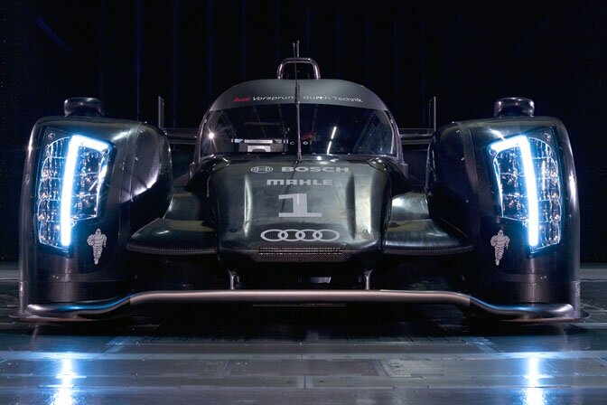
The R18 has been an imposing presence in sportscar racing. While both the Peugeot 908 and Toyota TS030 have beaten it in short distance races, the R18 has so far (at time of writing) proven to be unbeatable at Le Mans.
REVS AND LOADS
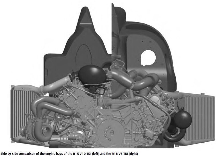
Because of the use of the mono turbocharger, it was necessary to increase the cylinder bank angle from the 90 degrees seen on the R10 and R15 to 120 degrees for the R18. This proved to be a very good compromise for
the overall package concerning the centre of gravity position and sufficient stiffness for the fully-stressed engine as part of the whole car.
The number of main bearings reduced from six to four because of the number of cylinders. At the same time, the bore was increased by 3.5 per cent and, in addition, the maximum combustion pressure increased,
which actually would have had to lead to higher bearing loads. However, by exploiting intelligent lightweight design for the entire crank mechanism, as well as clever mass distribution, it was possible to
maintain the bearing loads level from the R15 in the R18.
With increasing revs, the maximum bearing loads reduce due to the ever-increasing inertia forces, while the mean bearing loads increase. The change of the cylinder bank angle, however, leads to an increase
in bearing forces in the lateral direction. Particular effort was necessary from the design side to prevent sliding in the joint.
For lower revs, this effect is even more apparent due to the dominating gas forces, in the upper rev range the effect reduces because of the revolving inertia forces.